
tC -> FR-S.....and I am back!
 04-29-2014, 11:00 AM
#1781
Senior Member

SL Member
Thread Starter

Join Date: Mar 2011
Location: Nashua, NH
Posts: 2,102
 09-23-2014, 02:24 AM
#1782
Junior Member

Join Date: Feb 2014
Posts: 2
Converting Regular LED 7443 to CK type DIY#2
I bought this:
2X 7443 7444 Super Red 68 SMD Tail Stop Light LED Bulbs | eBay
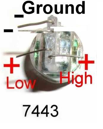
Now these 2 diagrams have been floating aroung the internet and are provided by superbrightleds and they are both wrong:
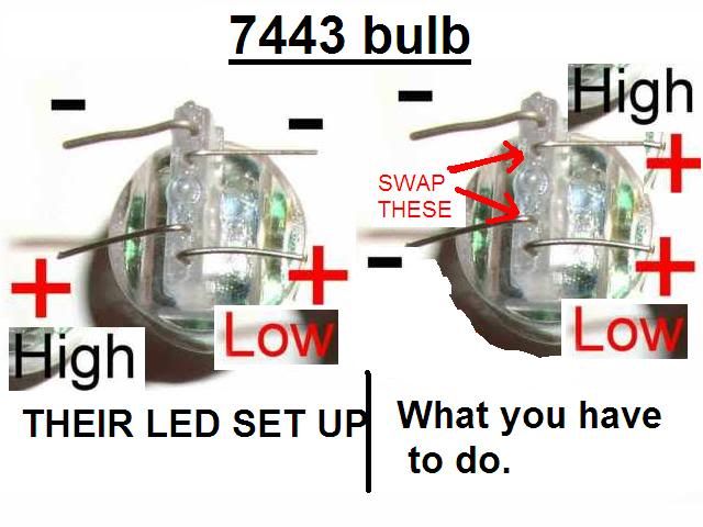
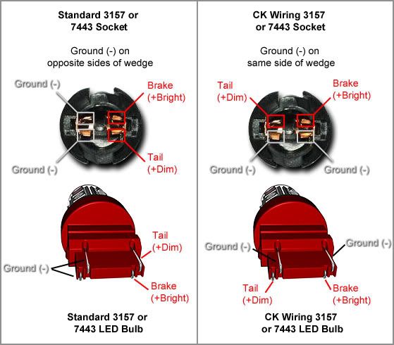
In each picture, on each LED they messed up the Tail and Brake! Which in turn makes the diagram work for a wrong reason.......
In the socket below, the ground is Black/white, Green/white is brake and Green is Tail.
SOOO
If ground is on the top then brake is on left and tail on right, which the opposite in each of the diagrams.
To prove that the Regular LED wiring is wrong as well I used a 12V source and connected it to the Tail which produced moderate light and then took another 12V lead and connected it to the brake and it was glowing very bright!
First time I tried it(when I was following the diagram), it did not work, because the LED doesn't allow you to do it the other way around.
So the tail and the brake on the Regular LED were flipped as well. The brake was the one at the edge.
The best way to find Ground on the LED is to Check for Continuity between 2 leads until you find it.
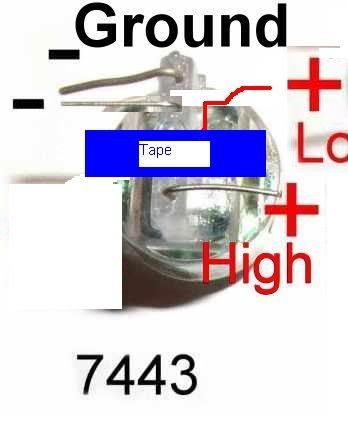
So here is the corrected Diagram:
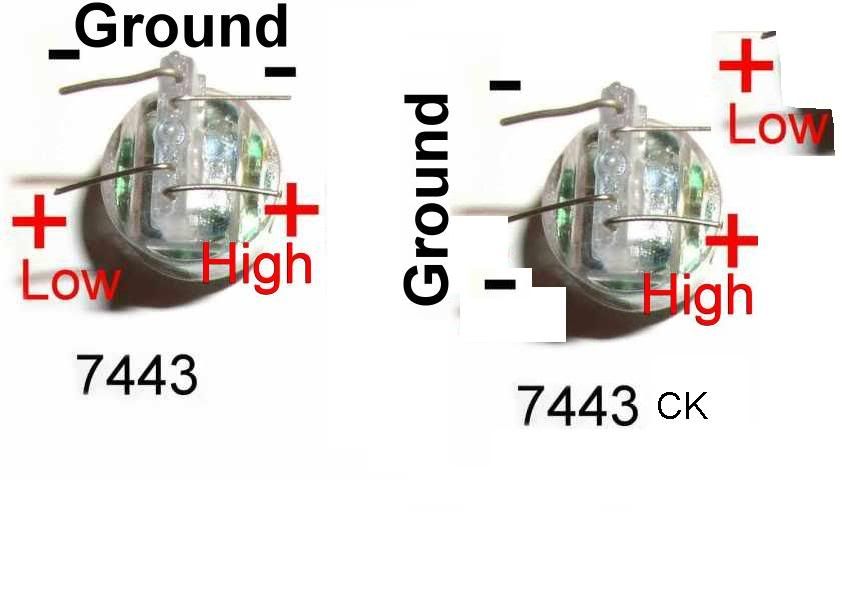
STEP1:
Bring the grounds on the same side, the side opposite from where the brake is:

Step2:
Cut the Tail light lead a little bit and solder an insulated wire to it. Solid 24 gauge wire works great. Then route it to the other side as far away from the brake as possible. Place some electrical tape over the soldering point:
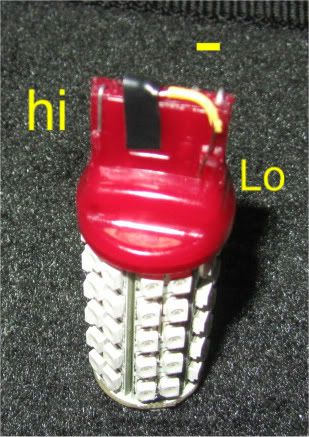
So now it looks like :
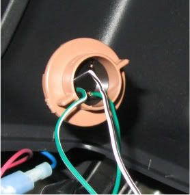
Step 3. Make sure to find the ground on the socket and Plug in the bulB!
Notice that the ground side of the socket is different loking from the other one.
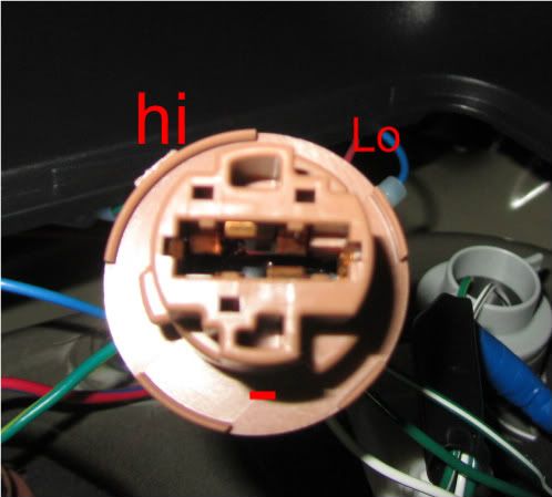
You may have to wiggle it a bit to get the wires to contact
YOU'RE DONE
I bought this:
2X 7443 7444 Super Red 68 SMD Tail Stop Light LED Bulbs | eBay
Now these 2 diagrams have been floating aroung the internet and are provided by superbrightleds and they are both wrong:
In each picture, on each LED they messed up the Tail and Brake! Which in turn makes the diagram work for a wrong reason.......
In the socket below, the ground is Black/white, Green/white is brake and Green is Tail.
SOOO
If ground is on the top then brake is on left and tail on right, which the opposite in each of the diagrams.
To prove that the Regular LED wiring is wrong as well I used a 12V source and connected it to the Tail which produced moderate light and then took another 12V lead and connected it to the brake and it was glowing very bright!
First time I tried it(when I was following the diagram), it did not work, because the LED doesn't allow you to do it the other way around.
So the tail and the brake on the Regular LED were flipped as well. The brake was the one at the edge.
The best way to find Ground on the LED is to Check for Continuity between 2 leads until you find it.
So here is the corrected Diagram:
STEP1:
Bring the grounds on the same side, the side opposite from where the brake is:
Step2:
Cut the Tail light lead a little bit and solder an insulated wire to it. Solid 24 gauge wire works great. Then route it to the other side as far away from the brake as possible. Place some electrical tape over the soldering point:
So now it looks like :
Step 3. Make sure to find the ground on the socket and Plug in the bulB!
Notice that the ground side of the socket is different loking from the other one.
You may have to wiggle it a bit to get the wires to contact
YOU'RE DONE
This is how it works: The original light has two actual filaments inside. When park is on, it does not leak to the brake circuit.
Led has one filament but controlling the power input to it you can get different level of brightness. So if park is on, it actually leaks the low current to the brake circuit because they uses the same filament. Guest what.... the 3rd brake light is also lit a bit and goes brighter when you hit the brake.
Trouble: Computer of the vehicle senses that there is power/current running on the brake system but you don't actually hit the brakes. When time comes to hit the brakes, the ABS light on dashboard comes on and won't turn off because their is current in the brake circuit. Turn off then turn on the car and everything is normal again until you hit the brakes again.
Solution: A diode is needed along the brake circuit just before the bulb so that the current of the parking circuit does not go across the brake circuit. You need two for left and right.

Thread
Thread Starter
Forum
Replies
Last Post
ScionLife Editor
Scion News Forum
0
03-21-2015 03:10 PM
cid_mcdp
Maintenance & Car Care
4
01-05-2015 02:45 PM