
'08/'09 Subwoofer Adjustment Project
 08-02-2008, 10:18 PM
#1
Senior Member
SL Member
Thread Starter

Join Date: May 2008
Location: West Lafayette, IN
Posts: 680
The Problem

I've got an '09 with the (weaksauce) stock subwoofer. Eventually I want to toss in the eD Stealth box to get some real bass, but for now I'm stuck with the stock system. I'd like to do a little tweaking to it though to improve its response. While the largest problem with it is obviously its (lack of) power handling, the low pass filter used by the amplifier for this sub allows frequencies not to my liking.
The Solution
Since there is no crossover adjustment, I'm left to my own creativity. My goal is to design a bandpass filter and put it in series with the amplifier to improve the response of the sub.
-------------------------------------------------------------------------
Step 1 - Find the Right Frequency Range
To find what range of frequencies the sub can hit properly, I generated a .wav file of test tones using Audacity (http://audacity.sourceforge.net/) ranging from 150Hz down to 20Hz. If you're interested in using this for yourself, PM me and I can send you the file, or show you how to generate your own in Audacity.
While I didn't use an oscilloscope to measure the response, I was able to pretty clearly determine what range I want to be played by the sub. My goal is a range that won't overlap with the midrange speakers (too much), and not hitting so low that it sounds god-awful. To my ears, this turned out to be 40Hz - 110Hz . While an ideal sub system wouldn't hit above 80Hz, that's about where this one peaks out. The range is a little higher, so I decided to keep a little more high end than you would normally want.
Step 2 - Filter Design!
I'm a junior in electrical engineering, so this was a real-world test of all those circuits classes I'm in at Purdue By doing some simple MATLAB scripting I've been able to design a transfer function for a Butterworth band pass filter to my specs. If there are any other nerds out there that are interested, I can post the script.
So, after doing some experimentation in MATLAB and PSPICE, I've decided the simplest and most effective route is a simple LC low-pass filter instead of a bandpass. With such a narrow frequency range, I'd need a very high-order Butterworth filter which would probably cause more problems than it would solve.
Step 3 - Circuit Realization
Here's the simple circuit I settled on, with the sub modeled by the 2-ohm resistor on the right:

And the frequency response from 1-200Hz for said circuit:
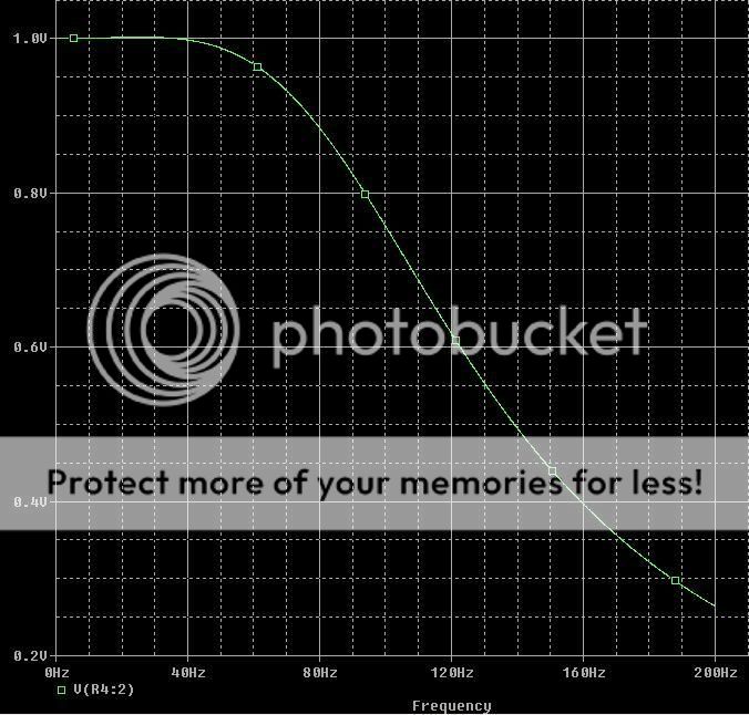
I'll be losing a little bit of power from 80-100Hz, but I should be able to crank it a little more with the loss of power from above 120Hz to make up for it.
Step 4 - Installation
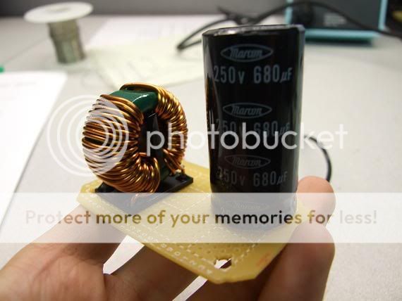

Had a 4.0mH inductor and 680uF cap on hand. The capacitor measured to be ~590uF on an LCR meter, so that's fairly close to what I need. A larger cap will just increase the gain a tiny bit anyways, so a little bigger is fine. Now I just need to put the sub in parallel with the cap and put in the amp connections and I should be set. I'll update later tonight with how it goes.
Step 5 - Testing
While playing the original test track, the filter filtered out signals about 120Hz. However, the sound quality of the subwoofer was absolutely horrid, and a lot of power was lost. I somewhat expected this, since I installed the filter behind the amp. By trying to filter the high-level signal, I most likely introduced a ton of noise and distortion. I will try again once I figure out the correct pins on the amp to splice into.
---------------------------------------------------------------------------
I still need the amp wiring diagram if anyone has it!
I've got an '09 with the (weaksauce) stock subwoofer. Eventually I want to toss in the eD Stealth box to get some real bass, but for now I'm stuck with the stock system. I'd like to do a little tweaking to it though to improve its response. While the largest problem with it is obviously its (lack of) power handling, the low pass filter used by the amplifier for this sub allows frequencies not to my liking.
The Solution
Since there is no crossover adjustment, I'm left to my own creativity. My goal is to design a bandpass filter and put it in series with the amplifier to improve the response of the sub.
-------------------------------------------------------------------------
Step 1 - Find the Right Frequency Range
To find what range of frequencies the sub can hit properly, I generated a .wav file of test tones using Audacity (http://audacity.sourceforge.net/) ranging from 150Hz down to 20Hz. If you're interested in using this for yourself, PM me and I can send you the file, or show you how to generate your own in Audacity.
While I didn't use an oscilloscope to measure the response, I was able to pretty clearly determine what range I want to be played by the sub. My goal is a range that won't overlap with the midrange speakers (too much), and not hitting so low that it sounds god-awful. To my ears, this turned out to be 40Hz - 110Hz . While an ideal sub system wouldn't hit above 80Hz, that's about where this one peaks out. The range is a little higher, so I decided to keep a little more high end than you would normally want.
Step 2 - Filter Design!
I'm a junior in electrical engineering, so this was a real-world test of all those circuits classes I'm in at Purdue
By doing some simple MATLAB scripting I've been able to design a transfer function for a Butterworth band pass filter to my specs. If there are any other nerds out there that are interested, I can post the script.So, after doing some experimentation in MATLAB and PSPICE, I've decided the simplest and most effective route is a simple LC low-pass filter instead of a bandpass. With such a narrow frequency range, I'd need a very high-order Butterworth filter which would probably cause more problems than it would solve.
Step 3 - Circuit Realization
Here's the simple circuit I settled on, with the sub modeled by the 2-ohm resistor on the right:
And the frequency response from 1-200Hz for said circuit:
I'll be losing a little bit of power from 80-100Hz, but I should be able to crank it a little more with the loss of power from above 120Hz to make up for it.
Step 4 - Installation
Had a 4.0mH inductor and 680uF cap on hand. The capacitor measured to be ~590uF on an LCR meter, so that's fairly close to what I need. A larger cap will just increase the gain a tiny bit anyways, so a little bigger is fine. Now I just need to put the sub in parallel with the cap and put in the amp connections and I should be set. I'll update later tonight with how it goes.
Step 5 - Testing
While playing the original test track, the filter filtered out signals about 120Hz. However, the sound quality of the subwoofer was absolutely horrid, and a lot of power was lost. I somewhat expected this, since I installed the filter behind the amp. By trying to filter the high-level signal, I most likely introduced a ton of noise and distortion. I will try again once I figure out the correct pins on the amp to splice into.
---------------------------------------------------------------------------
I still need the amp wiring diagram if anyone has it!

 08-05-2008, 11:48 PM
#7
Senior Member
SL Member

Join Date: Jan 2006
Location: San Diego (Mira Mesa), CA
Posts: 2,338
I'm a bit confused by your descriptions. Is this filter intended for before or after the amp? I ask because if it's pre-amp, you don't use a cap & inductor, but a cap & resistor. So is that the issue? Seems so...
08-06-2008, 08:29 PM
#9
Senior Member
SL Member
Join Date: Jan 2006
Location: San Diego (Mira Mesa), CA
Posts: 2,338
^Ok, then your topology is incorrect for a bandpass filter.
You said you wanted a bandpass filter, but your components are wired for lowpass only.
It's possible to do what you want with just the two components, but for a bandpass circuit they're BOTH supposed to be wired in series, NOT with the capacitor paralleled to the negative as you have it.
Additionally, I couldn't tell for certain from the pics, but it appears you're using a polarized capacitor, which won't work correctly for a passive audio filter, you need a non-poarized cap.
For a 110Hz low-pass and a 4-Ohm speaker, the value is approx. 275uF. That's only first order, such that it'll be -3dB at 110Hz and -6dB at 220Hz, which doesn't do much to avoid overlap with your main speakers in the front doors.
Regarding the 40Hz high-pass, the required inductor value is about 19.0mH. That'd be one HUGE inductor, and would rob a lot of power as well as add way too much load, which is why people don't use passive filters in such applications. Additionally, that would only be a 1st order 6dB/Oct. filter, such that it's -3dB at 40Hz and -6dB at 20Hz, not providing much filtering or protection from low frequencies for that little sub.
Seems like you need to get a bit more basic knowledge before making another attempt, so I'll just wish you luck with that.
If for some reason you decide you really want to implement that circuit, here's what you need;
18.0mH inductor $27
330uF capacitor $5
Since it's only a 1st order bandpass filter, these values will be better at meeting your requirements. Both components should be wired in series with the positive lead, inductor then cap, neither going to negative.
IMO, it's not worth the time, trouble and expense to do this, it likely won't improve SQ much, but the choice is yours.
08-07-2008, 12:48 AM
#10
Senior Member
SL Member
Thread Starter
Join Date: May 2008
Location: West Lafayette, IN
Posts: 680
I do have quite a bit of knowledge in this.
The trouble of getting an effective passive bandpass filter is why I went with just a lowpass. I was aware of this, just forgot to state it above. It was designed to be a lowpass -12dB filter at 120Hz, which it was. However, I was most likely incorrect as far as placement of the circuit, and possibly the capacitor used. I wasn't aware that the polarization mattered as long as it's wired in the correct polarization (it was), but I guess it does.
You're right, I don't have a lot of audio experience. However, I do have a fair amount of EE experience, which was what motivated me to try this and apply a bit of my knowledge. I probably could've done a bit more backround research into the application I was trying first, but I just wanted to give it a shot since it was a completely reversible "mod."
Sorry for not explaining my reasoning for switching to the lowpass filter, but trust me, I do have a good amount of knowledge on filters.
 08-07-2008, 01:27 AM
#12
Senior Member
SL Member
Thread Starter
Join Date: May 2008
Location: West Lafayette, IN
Posts: 680
Haha, surprised it took this long for someone to say that. Give me $400 for an SQ-10 stealth box and amp please?
It was just something that I found enjoyable and I was able to learn from.
It was just something that I found enjoyable and I was able to learn from.
08-07-2008, 02:06 AM
#14
Senior Member
SL Member
Thread Starter
Join Date: May 2008
Location: West Lafayette, IN
Posts: 680
Some people need their trunks for something besides headache inducing bass. I move myself every 4 months, and it fills up my car to the ceiling line. The stealth box is the perfect solution for someone who wants some bass but not sacrifice half of the interior volume of their car.
 08-08-2008, 08:21 PM
#16
Senior Member
SL Member
Join Date: Jan 2006
Location: San Diego (Mira Mesa), CA
Posts: 2,338
Originally Posted by rcf22
I do have quite a bit of knowledge in this.
The trouble of getting an effective passive bandpass filter is why I went with just a lowpass. I was aware of this, just forgot to state it above. It was designed to be a lowpass -12dB filter at 120Hz, which it was. However, I was most likely incorrect as far as placement of the circuit, and possibly the capacitor used. I wasn't aware that the polarization mattered as long as it's wired in the correct polarization (it was), but I guess it does.
You're right, I don't have a lot of audio experience. However, I do have a fair amount of EE experience, which was what motivated me to try this and apply a bit of my knowledge. I probably could've done a bit more backround research into the application I was trying first, but I just wanted to give it a shot since it was a completely reversible "mod."
Sorry for not explaining my reasoning for switching to the lowpass filter, but trust me, I do have a good amount of knowledge on filters.
The trouble of getting an effective passive bandpass filter is why I went with just a lowpass. I was aware of this, just forgot to state it above. It was designed to be a lowpass -12dB filter at 120Hz, which it was. However, I was most likely incorrect as far as placement of the circuit, and possibly the capacitor used. I wasn't aware that the polarization mattered as long as it's wired in the correct polarization (it was), but I guess it does.
You're right, I don't have a lot of audio experience. However, I do have a fair amount of EE experience, which was what motivated me to try this and apply a bit of my knowledge. I probably could've done a bit more backround research into the application I was trying first, but I just wanted to give it a shot since it was a completely reversible "mod."
Sorry for not explaining my reasoning for switching to the lowpass filter, but trust me, I do have a good amount of knowledge on filters.
Where/how did you determine your component values? Where you used 4.2mH & 560uF, the correct values are 7.5mH and 240uF for 120Hz lowpass on a 4 Ohm driver. If you use the correct component values, your results should improve greatly.
Yes, the polarization is important, because polarized implies a DC circuit. Audio signals are AC, thus the requirement for non-polarized caps, allowing bi-directionality.
EE knowledge is a great thing in general, and implementing it enables a person to learn quite a bit more, especially when it comes to audio applications, so keep trying!
08-08-2008, 08:26 PM
#17
Senior Member
SL Member
Thread Starter
Join Date: May 2008
Location: West Lafayette, IN
Posts: 680
That fact about polarization is obvious in hindsight, I didni't consider that.
Yes, those are the correct values for a 4 Ohm driver... I got various measurements of the resistance of the speaker ranging from 4Ohm to 1.6Ohm though, so I used that for a 2Ohm. Not sure if using the different values would improve a ton, but a non-polarized cap would obviously help.
I'll give this another shot when I get my hands on those components and let you know how it goes.
08-09-2008, 12:05 AM
#18
Senior Member
SL Member
Join Date: Jan 2006
Location: San Diego (Mira Mesa), CA
Posts: 2,338
^ Oh, in that case, the values you selected aren't too bad for a 2 Ohm driver.
However, you don't really want to measure the load while it's varying. Get the 'nominal' resistance (usually between 3 & 4 Ohms for a "4 Ohm" rated driver), then design your filter for that load.
If you're concerned about the impedance varying with frequency, the best way to address that is by implementing an impedance compensation network, AKA "Zobel circuit" or "conjugate network", which consists of a resistor & capacitor, wired from positive to negative, after the filter. Put another way, you don't design filters based on the varying loads observed during a frequency sweep, instead you implement a zobel to ensure the impedance remains the same throught the driver's passband. Done this way, the filter will funtion as intended, and is easy to model by getting the component values from a standard chart.
Once you complete this exercise, then you can get into the different types of crossovers. I'm not implying more complex 3rd or 4th order designs, but different topologies and types, such as Butterworth, Bessel, L-R and others. There are so many possibilities, with none necessarily being right or wrong, but all have their place and it's your choice as the system designer. As long as it sounds right to your ears, then it's effectively good.
I'm actually glad to see you or anyone else here make an attempt at creating their own passive filters. Even when wanting "components" (the term many use for a mid-tweeter set), there's no reason a person can't get whatever mids & tweeters they want, then design & build their own passive crossovers (simply high & low pass filters), they don't have to buy a "plug & play" set of whatever brand they want.
08-12-2009, 01:09 AM
#20
Senior Member
SL Member

Join Date: Jun 2009
Location: Evanston, IL
Posts: 231
I'd really like to know how this turns out. I'm getting kinda ____ed with the crossover of the stock sub, but at the same time don't quite care enough to buy an aftermarket sub. Hope this works out!